LED — indicator light
LED is for a single indicator light: a warning lamp, a caution legend, a gear light, anything
in the cockpit that is simply on or off. Your LED copies the lamp in the sim, so when the FIRE
warning lights up in DCS, the one on your panel lights up too, and when the sim's goes out, so
does yours.
Not quite the right part?
- A backlight that dims with the cockpit's lighting knob? Use Dimmer.
- A gauge needle? Use NeedleGauge.
- A number readout, like the drums on a radio? Use DrumDisplay.
- Your own display or gadget, something none of these cover? Use IntegerOutput, which hands the value to your own code.
In your sketch
const PinRef FIRE_LIGHT_PIN = PinRef(PB0);

OpenSkyhawk::LED fireLight(A_4E_C_D_GLARE_FIRE, A_4E_C_D_GLARE_FIRE_AM, FIRE_LIGHT_PIN);
These two lines go near the top of your sketch, above setup(), and they are all the code a
light needs. From then on the board switches the LED on and off by itself whenever the lamp in
the sim changes.
The first line says where the LED is wired — here, pin PB0 on the board. This is its
pin address, and it is the only part that changes if you plug the LED in
somewhere else. The second line creates the light. fireLight is a name you choose, and the two
names after it say which cockpit lamp to follow. They always come as a pair: the lamp's name, then
the same name again with _AM on the end, which picks your lamp out of the group DCS sends it in
(see Going further). DCS-BIOS Integration explains
where to find these names.
Wiring
Every indicator LED is wired the same way:
- The pin to a 330 Ω resistor.
- The other end of the resistor to the LED's long leg.
- The LED's short leg to GND.
An LED on its own will draw as much current as it can get, which can burn out the LED and the pin driving it. The resistor holds it to about 4 mA, which is plenty for an indicator lamp and well within what any pin on the board, an expander or a shift register can supply. LEDs only work one way round, so if one stays dark, the first thing to check is that the short leg goes to GND.
Pick the tab that matches where you've plugged the LED in. The wiring is the same in every one; only the pin address changes.
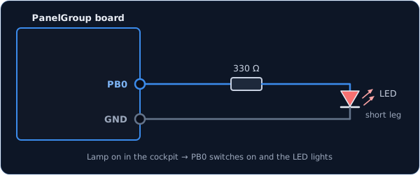
You can use any free pin on the board except PC14, which is too weak to light an LED. Each
pin has its name (PA0, PB1, and so on) printed next to it, and that name is what goes in
the pin address.
const PinRef FIRE_LIGHT_PIN = PinRef(PB0);
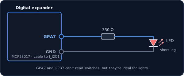
Every expander pin can drive a light, including GPA7 and GPB7. Those two can't read
switches, so lights are the perfect job for them.
const PinRef FIRE_LIGHT_PIN = PinRef(expander1, PORT_A, 7); // GPA7
If this is your first expander, your sketch also needs a couple of lines to set it up. Setting up a digital expander walks through them.
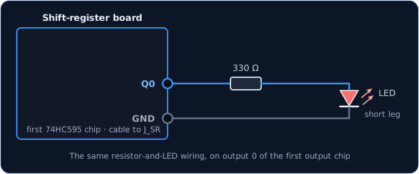
Lights go on the output chips in the chain, the 74HC595s. They're counted separately from the input chips, so the first output chip is chip 0 even if there are input chips before it.
const PinRef FIRE_LIGHT_PIN = PinRef(ShiftBus1, 0, 0); // first output chip, pin 0
Setting up a shift-register chain explains how the chips are numbered.
Troubleshooting
The LED never lights. It is most likely in backwards. Turn it round so the short leg (the flat side of the case) goes to GND. Also check that the cockpit lamp really is lit in the sim — your LED stays dark until DCS is running and tells it otherwise.
The LED is lit when the cockpit lamp is off.
Your LED is wired the other way round from the steps above: its long leg goes to 3.3V and the pin
switches its short leg. Rather than rewiring it, add true at the end of the line and the board
will flip it for you:
OpenSkyhawk::LED fireLight(A_4E_C_D_GLARE_FIRE, A_4E_C_D_GLARE_FIRE_AM, FIRE_LIGHT_PIN, true);
A different lamp's light comes on.
The two names don't match. Both must be the same lamp — A_4E_C_D_GLARE_FIRE with
A_4E_C_D_GLARE_FIRE_AM, not with another lamp's _AM.
A blue, white or green LED is very dim. These colours need almost all of the 3.3V just to light, which leaves nothing for the resistor to work with. Red, yellow and orange LEDs are the right choice for indicator lamps.
Going further
When the board starts up, every light is switched off and stays off until DCS sends its first update. That happens as soon as the board connects, so your panel catches up with the cockpit within a moment of DCS running.
The two names come as a pair because DCS doesn't send its lamps one at a time. It packs them
into groups of up to sixteen and sends a whole group at once — the fire warning shares its
group with fifteen other lamps, including the gear light and the rest of the glareshield
warnings. The first name picks the group and the _AM name picks your lamp out of it, so you
never have to work anything out yourself.
The true at the end of the line is for panels whose circuit board ties every LED's long leg
to 3.3V and lets the pin switch the short leg to GND. Both ways work equally well; true just
tells the board which one you used.
The 330 Ω resistor suits one small indicator LED. Anything hungrier — a bright lamp, several LEDs on one pin, or a light powered from 5V or 12V — needs a small transistor between the pin and the light. The Hardware Standards page has the rule for shift-register outputs.
Every detail of the class is in the API reference.