Switch3Pos — three-position switch
Switch3Pos is for a toggle switch with three positions: up, middle and down. You'll often see
these sold as ON–OFF–ON switches, and the spring-loaded kind that snaps back to the middle when
you let go works just the same. The cockpit switch follows yours to all three positions, so the
middle is a real position too, not just "neither end".
Not quite the right part?
- Only two positions (ON–OFF)? Use Switch2Pos.
- A rotary knob that clicks between positions, with a pointer? Use SwitchMultiPos for up to 12 positions, or AnalogMultiPos for more than 12.
- A knob with no pointer that turns forever and clicks as it goes? That's a rotary encoder — use RotaryEncoder.
In your sketch
const PinRef BOMB_ARM_PIN_A = PinRef(PA0);
const PinRef BOMB_ARM_PIN_B = PinRef(PA1);

OpenSkyhawk::Switch3Pos bombArm(DCSIN_ARM_BOMB, BOMB_ARM_PIN_A, BOMB_ARM_PIN_B);
These lines go near the top of your sketch, above setup(). A three-position switch needs two
wires, one for each end of its travel, so it gets two pin addresses
instead of one — here pins PA0 and PA1 on the board.
The last line creates the switch. bombArm is a name you choose, and DCSIN_ARM_BOMB is the
cockpit control it operates, the bomb arm switch. The order of the two pins matters: when the
switch connects the first pin, the cockpit switch goes to one end, and when it connects the
second pin, it goes to the other. With neither connected, it sits in the middle.
Wiring
A three-position switch has three legs, and it's wired like this:
- The middle leg to GND.
- One outer leg to the first pin, the other outer leg to the second pin.
- A 10 kΩ resistor from each pin to 3.3V — two resistors in all.
The middle leg is the switch's common: moving the lever connects it to one outer leg or the other, and in the middle position it connects to nothing. The board tells the three positions apart by which pin, if either, is connected to GND. Each pin needs its own pull-up resistor for the same reason a two-position switch does, because without one a pin that isn't connected to anything flickers at random.
Where the two pins are depends on what you've plugged the switch into. Pick the tab that matches your build — the wiring and the code look almost identical in each one.
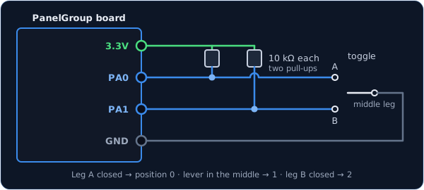
You can use any two free pins on the board. Each one has its name (PA0, PB1, and so
on) printed next to it, and that name is what goes in the pin address.
const PinRef BOMB_ARM_PIN_A = PinRef(PA0);
const PinRef BOMB_ARM_PIN_B = PinRef(PA1);
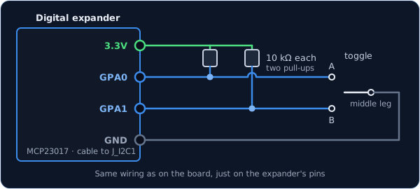
The wiring is exactly the same as on the board, just on two of the expander's pins. Any pins
work except GPA7 and GPB7, which can't read switches because of a fault in the chip.
const PinRef BOMB_ARM_PIN_A = PinRef(expander1, PORT_A, 0);   // GPA0
const PinRef BOMB_ARM_PIN_B = PinRef(expander1, PORT_A, 1);   // GPA1
If this is your first expander, your sketch also needs a couple of lines to set it up. Setting up a digital expander walks through them.
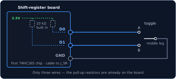
Here you only need three wires. Shift-register boards come with the pull-up resistors already fitted, so the outer legs go straight to two inputs and the middle leg to GND.
const PinRef BOMB_ARM_PIN_A = PinRef(ShiftBus1, 0, 0);   // first chip, pin 0
const PinRef BOMB_ARM_PIN_B = PinRef(ShiftBus1, 0, 1);   // first chip, pin 1
Setting up a shift-register chain explains how the chips are numbered.
Troubleshooting
The switch flickers, or DCS never sees it change. This is almost always a missing pull-up resistor. Check that each of the two pins has its own 10 kΩ resistor to 3.3V.
The cockpit switch goes up when mine goes down. The two pins are the wrong way round for this switch. Rather than rewiring it, swap the two pin addresses in the last line:
OpenSkyhawk::Switch3Pos bombArm(DCSIN_ARM_BOMB, BOMB_ARM_PIN_B, BOMB_ARM_PIN_A);
One end works, but the other end shows as the middle. The leg on GND isn't the middle one. On some switches the common leg isn't where you'd expect, so find it with a multimeter: it's the leg that connects to an outer leg in both end positions. Put that one on GND.
My switch has six legs. It's really two switches side by side that move together. Wire one row of three legs as shown above and leave the other row empty.
Going further
Like every switch, a change only counts once the switch has stayed put for 20 ms, which
filters out the bounce as the contacts close. The sim receives the position as a number:
0 when the first pin is connected, 1 in the middle and 2 when the second pin is
connected.
If the two pins somehow both read as connected at once — which a real switch can't do, so it only happens for an instant during a bounce — the first pin wins.
If you wire the middle leg to 3.3V instead of GND, with the resistors going to GND, add
true at the end of the line and the board will read it the other way round. To change the
20 ms settling time, add a number of milliseconds after that true, or after false if
your switch is wired the usual way.
When the board starts up, and whenever DCS asks for it, every switch reports its current position, so the sim catches up with anything you moved while it wasn't running.
Every detail of the class is in the API reference.