AnalogMultiPos — rotary selector on one wire
AnalogMultiPos reads a rotary selector switch — a knob that clicks between positions, with a
pointer showing which one is selected — through a single wire. Instead of giving every position
its own pin, you fit a chain of resistors called a resistor ladder behind the switch, so each
position puts a different voltage on one pin. That makes it the way to wire a selector when you
don't have a pin to spare for every position, or when it has more than 12 positions, and the
cockpit knob turns to the same position as yours.
Not quite the right part?
- 12 positions or fewer, and pins to spare? Use SwitchMultiPos, which gives each position its own wire. There are no resistors to match and nothing to measure.
- A knob with no pointer that turns forever and clicks as it goes? That's a rotary encoder — use RotaryEncoder. Each click steps the cockpit selector one position.
- A knob that turns smoothly, without clicks? That's a potentiometer — use AnalogInput.
- A toggle lever rather than a knob? Use Switch2Pos for two positions or Switch3Pos for three.
In your sketch
const PinRef WEAPON_SEL_PIN = PinRef(PA0);

OpenSkyhawk::AnalogMultiPos weaponSel(DCSIN_ARM_FUNC_SEL, WEAPON_SEL_PIN, 7);
These two lines go near the top of your sketch, above setup(). The first is the
pin address of the one wire that carries the whole knob, here pin PA0
on the board. It has to be a pin that can measure a voltage, not just tell on from off.
The second line creates the selector. weaponSel is a name you choose, DCSIN_ARM_FUNC_SEL is
the cockpit control it operates, the weapon function selector on the armament panel, and 7 is
how many positions the knob has. Because the ladder spaces the positions in equal steps from 0 V to 3.3 V, that number
is all the board needs to work out which position you've picked.
Wiring
For a knob with 7 positions, you need 6 identical resistors — always one fewer than the positions:
- Chain the 6 × 1 kΩ resistors end to end, and connect one end of the chain to 3.3V and the other to GND.
- Connect the switch's position legs to the chain in order: the first position to the GND end, each next position to the next joint between two resistors, and the last position to the 3.3V end.
- Connect the switch's common leg to the pin.
- Fit a 100 nF capacitor from the pin to GND.
The chain is called a ladder because each joint, or rung, sits one equal step higher in voltage than the one below it, from 0 V at the bottom to 3.3 V at the top. As you turn the knob, the common leg moves from rung to rung, so the board measures a different voltage at every position and works out which one you picked. Use resistors that are all the same value, ideally with 1% tolerance, because the steps are only equal if the resistors are.
The capacitor deals with the moment between clicks, when most switches briefly connect the common leg to nothing at all. It holds the last voltage steady for that instant, so the board doesn't misread the knob as it moves. The top of the ladder must go to 3.3V, never 5V, which can damage the pin.
Where the pin itself is depends on what you've plugged the ladder into. Pick the tab that matches your build — the wiring and the code look almost identical in each one.
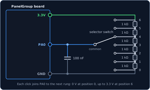
Only some of the board's pins can measure a voltage: PA0 to PA5, PB0 and PB1. They
are marked on the board, and any free one will do.
const PinRef WEAPON_SEL_PIN = PinRef(PA0);
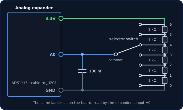
The wiring is exactly the same as on the board, on one of the expander's inputs A0 to
A3.
const PinRef WEAPON_SEL_PIN = PinRef(adc1, 0); // input A0
If this is your first analog expander, your sketch also needs a couple of lines to set it up. Setting up an analog expander walks through them.
Custom positions
The board measures the ladder as a number from 0 to 65535, from the GND end to the 3.3V end. With the short line at the top of this page, the class assumes the positions are evenly spaced across that range, which is exactly what a ladder of identical resistors gives. For this 7-position knob, it expects readings of about 0, 10923, 21845, 32768, 43690, 54613 and 65535.
Sometimes the steps aren't even — a selector that came with its own resistors, a ladder built from whatever values you had, or a knob that skips some of the cockpit's positions. Then you give the class a list instead, with the reading you actually get at each position:
const uint16_t WEAPON_SEL_READINGS[] = {
    0, 9800, 21000, 32700, 43900, 55200, 65535,
};

OpenSkyhawk::AnalogMultiPos weaponSel(DCSIN_ARM_FUNC_SEL, WEAPON_SEL_PIN, 7,
                                      WEAPON_SEL_READINGS);
The list has one number per position, in order from the first position to the last, and the
class places each position at its own number rather than assuming equal steps. If a position on
the cockpit knob has no click of its own on yours, put ANALOG_NC in its place: the board never
reports it, and its neighbours share its space.
To find your numbers, temporarily swap the selector's line for a plain knob,
OpenSkyhawk::AnalogInput probe(DCSIN_ARM_FUNC_SEL, WEAPON_SEL_PIN);, and turn on the
debug stream. Each time you click
to a new position you'll see a line like [ANA] 0x8019: 32700. Note the number at each
position, then put the selector's line back with your list and
turn the debug stream off again.
Troubleshooting
The cockpit knob never moves, whatever position I pick.
The wire is on a pin that can't measure a voltage. Move it to one of PA0 to PA5, PB0 or
PB1, or to an analog expander. Digital expanders and shift registers can't read a ladder at
all.
The cockpit knob turns the opposite way to mine. The two ends of the ladder are swapped. Swap the wires going to 3.3V and GND at the ends of the chain, so the first position is at the GND end.
One position lands on its neighbour, or doesn't register at all. The steps of the ladder aren't even, usually because one resistor is the wrong value or a joint is poorly soldered. Check each resistor with a multimeter, or measure the positions and give the class a list, as described in Custom positions.
The cockpit knob jumps about while I'm turning mine. The 100 nF capacitor from the pin to GND is missing. Without it, the pin is connected to nothing between clicks and the board reads whatever noise it picks up.
Going further
The board divides the full range of readings, 0 to 65,535, into a band for each position. Each band reaches half-way to its neighbours, minus a small gap of 1,000 at each edge. A reading that falls in a gap keeps the last position, so a knob sitting near a boundary can't flicker between two. One more number at the end of the line changes the size of that gap.
The board reads the knob every 8 ms. Unlike a switch, there's no 20 ms settling time, because the gaps between the bands already do that job.
The sim receives the same thing as from a SwitchMultiPos: the number of the selected position, starting from 0. When the board starts up, and whenever DCS asks for it, it reports the knob's current position.
Every detail of the class is in the API reference.