RotaryEncoder — rotary encoder
RotaryEncoder is for a rotary encoder: a knob that turns forever in both directions, with a
small click you can feel at each step. An encoder doesn't know where it's pointing, only that it
moved one click this way or that, so the board passes each click on to DCS as "one step up" or
"one step down". The cockpit control moves by one step for every click, and DCS keeps track of
where it ends up. It can step a selector or nudge a knob — you pick which in your sketch.
Not quite the right part?
- Does the cockpit knob have a pointer or marked positions? Use a selector switch instead: SwitchMultiPos for up to 12 positions, or AnalogMultiPos for more. A selector knows where it is pointing, so the sim matches it at startup; an encoder can't tell the sim where it is, only that it moved.
- A knob you'll spin a lot, such as winding in a latitude? Use RotaryAcceleratedEncoder, which takes bigger steps when you spin it fast.
- A knob that stops at both ends (a potentiometer)? Use AnalogInput.
In your sketch
Pick the tab that matches the cockpit control. The wiring is the same for both; only the line in your sketch changes.
const PinRef FREQ_A_PIN = PinRef(PA0);
const PinRef FREQ_B_PIN = PinRef(PA1);

OpenSkyhawk::RotaryEncoder freq10MHz(DCSIN_ARC51_FREQ_10MHZ, FREQ_A_PIN, FREQ_B_PIN,
    OpenSkyhawk::EncoderStepsPerDetent::Four, OpenSkyhawk::EncoderMode::Dir);
This turns the UHF radio's 10 MHz frequency wheel. EncoderMode::Dir (short for
direction) makes every click one position up or one position down. Use this mode for any
selector whose position you read on a display rather than from a pointer on the knob.
const PinRef DEST_LAT_A_PIN = PinRef(PA0);
const PinRef DEST_LAT_B_PIN = PinRef(PA1);

OpenSkyhawk::RotaryEncoder destLat(DCSIN_DEST_LAT_KNB, DEST_LAT_A_PIN, DEST_LAT_B_PIN,
    OpenSkyhawk::EncoderStepsPerDetent::Four);
This turns the navigation computer's destination latitude knob. With no mode at the end, the encoder works in REL mode (short for relative), where every click nudges the knob by a fixed amount. That amount is the step size DCS-BIOS suggests for these knobs, and Troubleshooting shows how to change it if the knob feels too fast or too slow.
These lines go near the top of your sketch, above setup(), and they are all the code an
encoder needs. The first two lines are pin addresses for the encoder's
two signal pins, A and B. The last line creates the encoder itself: a name you choose,
the cockpit control it operates, and its two pins. Every DCS-BIOS control has a name like
DCSIN_DEST_LAT_KNB; DCS-BIOS Integration explains
where to find them.
EncoderStepsPerDetent::Four tells the board how your encoder counts: most encoders make four
tiny electrical changes for every click you feel, called a detent. If it takes two or four
clicks to move the cockpit control one step, see Troubleshooting.
Wiring
An encoder has three pins in a row, and every encoder is wired the same way:
- The middle pin, C, to GND. It is sometimes marked GND or COM.
- Pin A to one pin, and pin B to another.
- A 10 kΩ resistor from each of those two pins to 3.3V.
A and B are each a little switch to GND, so like any switch they need a pull-up resistor to stop them flickering when they're open. Don't worry about which of A and B goes where. If the knob turns the wrong way, you swap them in your sketch rather than on the wires. Many encoders also have two pins on the other side for a push-button built into the shaft; that is a separate switch, so wire it as a Switch2Pos or leave it unconnected.
Where A and B themselves go depends on what you've plugged the encoder into. Pick the tab that matches your build — the wiring is the same in each one, and only the two pin addresses change.
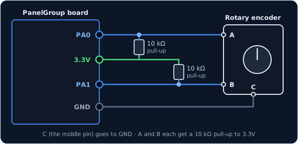
You can use any two free pins on the board. Each one has its name (PA0, PB1, and so on)
printed next to it, and those names go in the pin addresses.
const PinRef FREQ_A_PIN = PinRef(PA0);
const PinRef FREQ_B_PIN = PinRef(PA1);
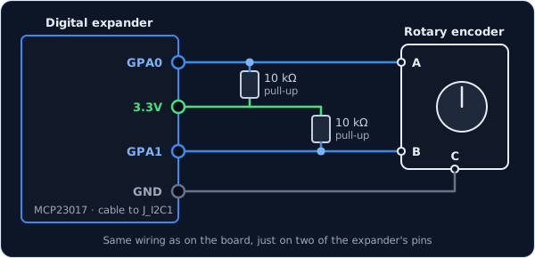
The wiring is exactly the same as on the board, just on two of the expander's pins. Any
pins work except GPA7 and GPB7, which can't read inputs because of a fault in the chip.
Make sure the expander's two interrupt wires are connected, as the setup guide shows, so
the board hears about every click straight away.
const PinRef FREQ_A_PIN = PinRef(expander1, PORT_A, 0);   // GPA0
const PinRef FREQ_B_PIN = PinRef(expander1, PORT_A, 1);   // GPA1
If this is your first expander, your sketch also needs a couple of lines to set it up. Setting up a digital expander walks through them.
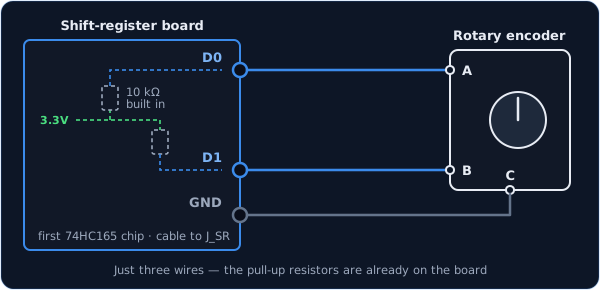
A shift register is the best place for an encoder, especially one you spin quickly. You only need three wires, because shift-register boards come with the pull-up resistors already fitted. Setting up a shift-register chain explains how the chips are numbered.
const PinRef FREQ_A_PIN = PinRef(ShiftBus1, 0, 0);   // first chip, pin 0
const PinRef FREQ_B_PIN = PinRef(ShiftBus1, 0, 1);   // first chip, pin 1
To get the full benefit, also add one line to your platformio.ini, under build_flags.
With it, the board never misses a click:
-DSHIFTBUS_ISR_HZ=1000
Troubleshooting
Turning the knob does nothing, or the cockpit control jumps about at random. Check that the middle pin goes to GND and that both A and B have their 10 kΩ resistor to 3.3V. A missing pull-up on either pin is enough to scramble every click.
It turns the wrong way. Swap the two pin addresses in the line. There's no need to touch the wires:
OpenSkyhawk::RotaryEncoder freq10MHz(DCSIN_ARC51_FREQ_10MHZ, FREQ_B_PIN, FREQ_A_PIN,
    OpenSkyhawk::EncoderStepsPerDetent::Four, OpenSkyhawk::EncoderMode::Dir);
It takes two or four clicks to move the cockpit control one step.
Your encoder makes fewer changes per click than the board expects. Change Four to Two (if it
took two clicks) or One (if it took four).
The wiring checks out, but the cockpit control never moves. The encoder is probably in the wrong mode for that control. Switch it from DIR to REL, or the other way round, and try again.
In REL mode, each click moves the knob too far. Add a smaller step size at the end of the line. Half the number moves the knob half as far per click, and a bigger number turns it faster:
OpenSkyhawk::RotaryEncoder destLat(DCSIN_DEST_LAT_KNB, DEST_LAT_A_PIN, DEST_LAT_B_PIN,
    OpenSkyhawk::EncoderStepsPerDetent::Four, OpenSkyhawk::EncoderMode::Rel, 1600);
Going further
An encoder only ever reports movement, never a position. So when the board starts up, or when DCS reconnects, the encoder sends nothing at all, which means it can never move the sim away from a mission's preset setting.
The board tells the direction from the order A and B change in. Turning one way, A changes just before B; turning the other way, B changes first. That's also why swapping them in the sketch reverses the knob.
You can also work out the steps per detent from the encoder's datasheet. If it lists the
same number of pulses per turn as detents per turn, use Four. If it has half as many
pulses as detents, use Two.
The two modes match how DCS-BIOS lists the control. A control listed as fixed_step
(it takes INC and DEC) wants DIR mode, and one listed as variable_step wants REL
mode.
On the board's own pins or on a digital expander, the board reads the encoder each time
round its main loop. That's plenty for normal turning, but if the loop is held up, for
example while it redraws a display, a fast spin can lose a click or two. A shift register
with SHIFTBUS_ISR_HZ reads on a timer instead, so it never misses one.
If you're coming from DCS-BIOS, you may be looking for RotarySwitch. There isn't one on
purpose: the DCS-BIOS version assumes it starts at position 0 and sends whole positions, so
the first click after a cold start can jump the sim away from a mission's preset. A
RotaryEncoder in DIR mode only ever says "one up" or "one down", so the sim keeps its
position. Because DCS keeps the position, it also stops the selector at its ends, and
turning past the last digit simply does nothing.
Every detail of the class is in the API reference.