SwitchMultiPos — rotary selector switch
SwitchMultiPos is for a rotary selector switch: a knob that clicks between a fixed set of
positions, with a pointer or markings showing which one is selected. Inside, the switch has one
leg for every position and a common leg that the knob connects to whichever position it's
pointing at. Each position gets its own wire, and the cockpit knob turns to the same position as
yours.
Not quite the right part?
- More than 12 positions, or not enough pins to give each one a wire? Use AnalogMultiPos, which reads the whole knob through a single pin.
- A knob with no pointer that turns forever and clicks as it goes? That's a rotary encoder — use RotaryEncoder. Each click steps the cockpit selector one position.
- A toggle lever rather than a knob? Use Switch2Pos for two positions or Switch3Pos for three.
In your sketch
const PinRef RADIO_MODE_PINS[] = {
    PinRef(PA0),   // position 0
    PinRef(PA1),   // position 1
    PinRef(PA2),   // position 2
    PinRef(PA3),   // position 3
};

OpenSkyhawk::SwitchMultiPos radioMode(DCSIN_ARC51_MODE, RADIO_MODE_PINS, 4);
These lines go near the top of your sketch, above setup(). The UHF radio's mode knob has four
positions, so it needs four pin addresses, and the first part keeps them
together in a list. The [] after the name says "this is a list", the curly braces hold the
addresses, and each one sits on its own line with a comma after it.
The order of the list is what tells the board which wire is which position. The first address is
the cockpit knob's first position, the next is the one after it, and so on round the dial. The
last line creates the selector: radioMode is a name you choose, DCSIN_ARC51_MODE is the
cockpit control it operates, and 4 is how many addresses are in the list. Keep the list at the
top of the sketch with everything else, because the selector reads from it the whole time the
board is running.
Wiring
Every selector is wired the same way:
- The common leg to GND.
- Each position leg to its own pin, in the same order as your list.
- A 10 kΩ resistor from every pin to 3.3V.
The common leg usually sits in the middle of the switch. Whichever position the knob points at, that position's leg is connected to GND, and every other leg is connected to nothing. That's why each pin needs its own pull-up resistor: like a two-position switch, a pin with nothing connected flickers at random unless a resistor holds it steady.
Many rotary switches have more legs than your cockpit knob has positions. Wire only the legs for the positions your knob actually reaches, and leave the rest empty.
Where the pins are depends on what you've plugged the selector into. Pick the tab that matches your build — the wiring and the code look almost identical in each one.
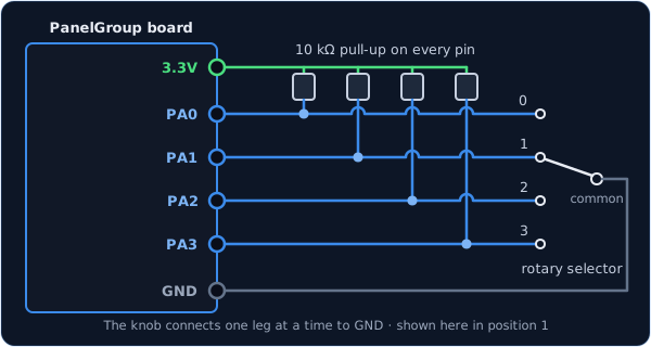
You can use any free pins on the board. Each one has its name (PA0, PB1, and so on)
printed next to it, and those names are what go in the list.
const PinRef RADIO_MODE_PINS[] = {
    PinRef(PA0), PinRef(PA1), PinRef(PA2), PinRef(PA3),
};
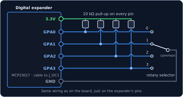
The wiring is exactly the same as on the board, just on the expander's pins. Any pins work
except GPA7 and GPB7, which can't read switches because of a fault in the chip.
const PinRef RADIO_MODE_PINS[] = {
    PinRef(expander1, PORT_A, 0),   // GPA0
    PinRef(expander1, PORT_A, 1),   // GPA1
    PinRef(expander1, PORT_A, 2),   // GPA2
    PinRef(expander1, PORT_A, 3),   // GPA3
};
If this is your first expander, your sketch also needs a couple of lines to set it up. Setting up a digital expander walks through them.
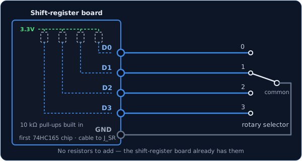
Shift-register boards come with the pull-up resistors already fitted, so each position leg goes straight to an input and the common leg to GND.
const PinRef RADIO_MODE_PINS[] = {
    PinRef(ShiftBus1, 0, 0),   // first chip, pin 0
    PinRef(ShiftBus1, 0, 1),   // first chip, pin 1
    PinRef(ShiftBus1, 0, 2),   // first chip, pin 2
    PinRef(ShiftBus1, 0, 3),   // first chip, pin 3
};
Setting up a shift-register chain explains how the chips are numbered.
Troubleshooting
The cockpit knob lands on the wrong position. The order of your list doesn't match the order of your wiring. Rather than rewiring the switch, rearrange the addresses in the list until each position lands where it should.
Turning to one position does nothing — the cockpit knob stays where it was. That position's leg isn't reaching its pin. When the board can't see any position, it keeps the last one, so a missing wire looks like the knob refusing to move. Check that leg's wire and its pull-up resistor.
The cockpit knob never moves at all. Check that the common leg is connected to GND. Without it, none of the position legs can ever connect anything.
Going further
Most rotary switches connect nothing at all for an instant as the knob moves between clicks. The board keeps the last position during that gap, so the sim never sees a stray jump. A new position only counts once the knob has rested there for 20 ms, so if you spin quickly past several positions, the sim goes straight to the one you stop on.
Some selectors have a position with no leg of its own, such as an OFF position that simply
connects nothing. Put PIN_NC ("nothing connected") in its place in the list, and the board
reports that position whenever none of the other legs is connected.
If you wire the common leg to 3.3V instead of GND, with the resistors going to GND, add
true at the end of the line and the board will read it the other way round.
SwitchMultiPos, AnalogMultiPos and Switch3Pos are
built on the same foundation, MultiPosInput, and send the sim exactly the same thing: the
number of the selected position, starting from 0. So you can rewire a selector from one
wire per position to a resistor ladder without changing anything on the DCS side. The shared
part is described in the
MultiPosInput API reference.
Every detail of the class is in the API reference.