AngleSensorInput — magnetic angle sensor knob
AngleSensorInput is for a knob with a small magnet on its shaft and a magnetic angle sensor
chip underneath, such as an AS5600 sensor board. The chip feels which way the magnet points and
turns that into a voltage, so it works like a potentiometer with nothing to rub or wear out. The
cockpit control follows yours smoothly, which suits knobs that have to sit at an exact spot, like
the gunsight elevation knob.
Not quite the right part?
- An ordinary potentiometer knob or slider? Use AnalogInput.
- A knob that clicks between a few fixed positions? Use SwitchMultiPos, or AnalogMultiPos if it's wired as a resistor ladder on a single pin.
- A knob that spins round and round without stopping? That's a rotary encoder. Use RotaryEncoder.
In your sketch
const PinRef GUNSIGHT_KNOB_PIN = PinRef(PA0);

OpenSkyhawk::AngleSensorInput gunsightKnob(DCSIN_GUNSIGHT_KNB, GUNSIGHT_KNOB_PIN, 135, 150);
These two lines go near the top of your sketch, above setup(). The first is the
pin address, which says the sensor's output is wired to pin PA0. In the
second, gunsightKnob is a name you choose, and DCSIN_GUNSIGHT_KNB is the cockpit control it
turns. DCS-BIOS Integration explains where these names
come from.
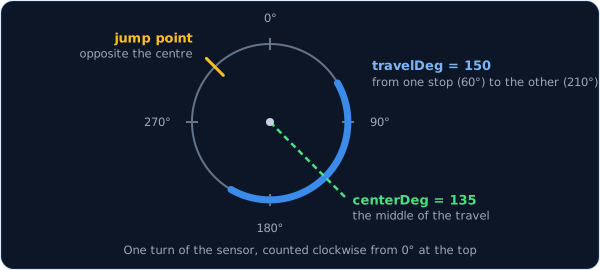
The last two numbers describe your knob, because the sensor reads a whole circle but your knob
only turns part of the way round it. 150 is the travel: how many degrees your knob turns
from one stop to the other. 135 is the centre: where the sensor points when your knob is
halfway between its stops. The class lines those up with the cockpit knob, so your knob's two
stops become the cockpit knob's two ends. Every build's numbers are different, because they depend
on how the magnet happens to sit on the shaft, so you'll
measure your own once the knob is wired.
Wiring
An AS5600 sensor board is wired like this:
- VCC to 3.3V.
- GND to GND.
- OUT to the pin.
- DIR to GND as well.
OUT is the sensor's answer, a voltage between 0 V and 3.3 V that follows the magnet round the
circle. DIR sets which way round the sensor counts, and the chip needs it connected to
something, otherwise the direction can flip at random. Always power it from 3.3V, never 5V, because
the sensor's output would then go above 3.3 V and damage the board's analog pins. The magnet sits
on the end of the knob's shaft, centred over the chip and a couple of millimetres above it.
Where the pin itself is depends on what you've plugged the sensor into. Pick the tab that matches your build — the wiring and the code look almost identical in each one.
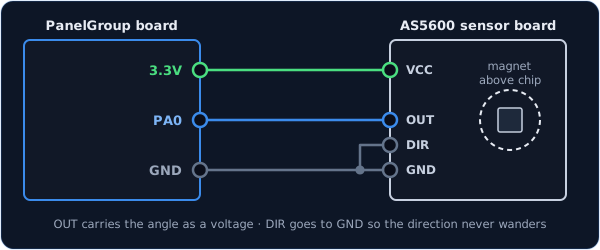
Only some of the board's pins can measure a voltage: PA0, PA1, PA2, PA3, PA4,
PA5, PB0 and PB1. They're marked as analog on the board.
const PinRef GUNSIGHT_KNOB_PIN = PinRef(PA0);
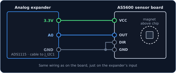
The wiring is the same, on one of the expander's four inputs, A0 to A3.
const PinRef GUNSIGHT_KNOB_PIN = PinRef(adc1, 0); // input A0
If this is your first analog expander, your sketch also needs a couple of lines to set it up. Setting up an analog expander walks through them.
Finding your two numbers
You find the centre and the travel on your desk, by letting the board tell you what the sensor reads. It takes five minutes, and you only do it once per knob.
-
Temporarily change the knob's line to a plain AnalogInput, which reports the sensor's raw reading. Then turn on the debug stream by adding one line at the start of
setup():OpenSkyhawk::AnalogInput gunsightKnob(DCSIN_GUNSIGHT_KNB, GUNSIGHT_KNOB_PIN); // just for measuring void setup() { STM32Board::setDebug(true); PanelGroup::setup(); } -
Upload the sketch and open the debug stream. Every time the knob moves, you'll see a line like
[ANA] 0x8055: 10920. - Turn the knob to its bottom stop — the end where the cockpit control should be at its lowest — and note the number. Then turn it slowly to the top stop and note that one. The number should go up as you turn; if it goes down instead, flip the sensor's direction (see Troubleshooting) and start this step again. If the number jumps from a big value to a small one partway through, that's just the sensor passing its own zero, and it's fine.
- Divide each number by 182 to turn it into degrees: these are your bottom and top angles.
- Work out the two numbers the class needs:
- Travel = top − bottom. If that comes out negative, add 360.
- Centre = bottom + half the travel. If that comes out over 360, take 360 away.
For example, if the stops read 10920 and 38220, that's 60° and 210°. The travel is
210 − 60 = 150, and the centre is 60 + 75 = 135.
The second rule is for a knob whose travel passes the sensor's zero. Say the stops read 61880
and 7280 — that's 340° and 40°. Then 40 − 340 = −300, so the travel is −300 + 360 = 60,
and the centre is 340 + 30 = 370, which is 10 once you take 360 away. The knob turns 60°
centred on 10°, not 300° centred on 190°, and the class handles the zero crossing for you.
Put your two numbers into the AngleSensorInput line, change it back from AnalogInput, and
you're done. You can leave the debug stream on while you test, but
turn it off again before you fly.
Troubleshooting
The cockpit knob turns the opposite way to mine.
Move the sensor board's DIR wire from GND to 3.3V, which makes the sensor count the other way
round. That changes every reading, so measure your two numbers again afterwards.
The cockpit knob hits its end too early, or never quite gets there. The travel or the centre doesn't match your knob. Measure them again as above, and make sure the magnet is glued or pinned firmly, so it can't slip on the shaft.
The cockpit knob jumps from one end to the other partway through the turn. The centre no longer matches your knob, usually because the magnet slipped on the shaft. Fix the magnet firmly in place, then measure your two numbers again as in Finding your two numbers.
The number in the debug stream wobbles all over the place, or barely changes. The magnet is too far from the chip, or not centred over it. Bring it to a couple of millimetres above the chip, directly over the middle.
Going further
Underneath, an AngleSensorInput is an AnalogInput with angle maths
added. It smooths the readings and ignores tiny wobbles in exactly the same way, and it
reports its position when the board starts up and whenever DCS asks. Unlike AnalogInput,
it doesn't take a reverse or dead-zone setting: the sensor's DIR pin sets the direction,
and the dead zone stays at the standard 128 steps. A joystick axis ID such as CTRL_ROLL
works in place of the cockpit control name, just as it does for AnalogInput.
A sensor that reads a whole circle has to have a jump somewhere, because 0° and 360° are the same place. The class moves that jump to the point directly opposite your centre, as far from your knob's travel as it can go. That's why the travel has to be less than a full turn.
The centre can even be given past 360°, so 370 means the same as 10. Past either end of the travel, the cockpit knob simply stays at its end.
The MT6701 sensor chip works too, through its analog output. Check your sensor board's notes for which pin that is and how to set its direction.
Every detail of the class is in the API reference.