Connector & Harness Guide
Two connector families cover the whole cockpit: Molex Mini-Fit Jr for power-class harnesses (main bus, backlight), JST-XH for signal-class legs (I²C, SPI, switches). Nothing smaller than 2.54 mm pitch is used anywhere, and no third family is ever introduced — every harness in the aircraft crimps with two tools (Mini-Fit Jr: JRready ST6490-ACT · JST-XH: Engineer PA-09).
Wire gauge: 16–18 AWG silicone on the main bus (power + CAN daisy-chain); 24 AWG on signal harnesses and backlight legs.
The interface-class standard
Harnesses standardize at the connector, not the silicon: a sub-panel that presents a clean I²C leg is a standard device whatever chips live inside it, and the same goes for an SPI leg. Each interface class has a unique pin count within its connector family, so a cable physically cannot mate with the wrong socket.
| Class | Pins | Family | Reaches |
|---|---|---|---|
CAN trunk + power (J_BUS_IN/J_BUS_OUT) |
8 (2×4) | Mini-Fit Jr | host boards only, daisy-chained |
Backlight single-zone (J_BL) |
2 (1×2) | Mini-Fit Jr | one dimming zone per cable |
| Backlight dual-zone + utility 5 V | 4 (2×2) | Mini-Fit Jr | gauge panels (two zones) |
I²C leg (J_I2C) |
8 | JST-XH | I²C-class sub-panels |
SPI leg (J_SR) |
7 | JST-XH | SPI-class sub-panels (chain end) |
Which signal leg does a sub-panel get? Physics decides: panels with rotary encoders or fast gauges take the SPI leg (shift-register I/O keeps encoder counting off the I²C bus — see Hardware Standards); everything else is legitimate on the I²C leg, whatever it uses internally (MCP23017, OLED, ADS1115).
Layers: the CAN trunk terminates only at host boards (the MCU carrier of each
controller). A sub-panel's complete interface is one signal leg plus a backlight cable.
Hosts may carry several parallel connectors of one class (two J_BL sockets on one zone,
two J_I2C on one bus) — sized per controller during schematic design. The exception is
the SPI leg: shift-register chains are series devices, so each host chain supports one
end-node leg (chain-through connectors are a future class, specified when a gauge-cluster
controller needs them).
Wires are not color-coded
Pin position is the only identification. The diagrams below are the build-time reference — crimp with the drawing open. All views look into the cable-housing mating face; the board header is the mirror image.
CAN trunk — J_BUS_IN / J_BUS_OUT
Molex Mini-Fit Jr 2×4 (5566-08A2 header / 5557 cable housing), two per host board,
bus passes straight through. See Mini-Fit Jr parts below.
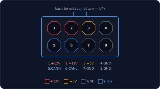
Pass-through pair on every host: J_BUS_IN ↔ J_BUS_OUT. 18 AWG, ≈8 A/pin all-loaded;
carries the per-console power feed. CANH/CANL share a row for clean differential routing.
View: into the cable-housing mating face, latch up; numbering per the Molex 5557 drawing.
The housing and header number mirror each other — build one harness and buzz it out end to
end before crimping the rest.
Backlight single-zone — J_BL
Molex Mini-Fit Jr 1×2 (5566-02A2), one per lighting zone, never mixed into a signal
harness.
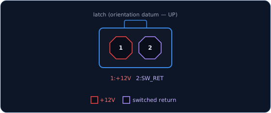
Low-side dimming: +12 V → LED string → SW_RETURN → zone MOSFET on the host. The return
is a switched line, not a ground. View: into the cable-housing mating face, latch up.
Backlight dual-zone + utility 5 V — gauge panels
Molex Mini-Fit Jr 2×2. Gauge-bearing panels carry two dimming zones — legend/panel markings and in-gauge instrument lighting — mirroring the aircraft's separate console and instrument dimmer circuits. Low-side switching makes each return supply-agnostic: a zone's string may hang on 12 V (legend strips) or 5 V (in-gauge LEDs).
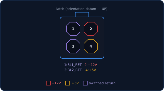
BL1 = legend zone, BL2 = gauge zone; both returns are switched lines to the host MOSFETs. The +5 V is a utility feed for small loads only (≲50 mA — driver logic, in-gauge LEDs); its return rides the panel's signal-cable GND. Servos never use it — servo panels buck locally from 12 V. View: into the cable-housing mating face, latch up; pin order is the proposed standard — verify against the Molex 5557 drawing before first crimp.
Mini-Fit Jr parts
The standard is Molex Mini-Fit Jr, 4.2 mm: 5566 board header, 5557 cable housing,
5556 crimp terminal (18–24 AWG). Board and cable parts must come from the same series.
Series ratings: 9 A / 300 V per circuit, contact resistance ≤20 mΩ initial, 30 °C max temperature rise at rated current, 30 mating cycles, −40 to +105 °C. Thirty cycles is the rated life — the trunk is not a frequently-demated interface.
The crimp tool is the JRready ST6490-ACT (see the table at the top of this page).
I²C leg — J_I2C1 / J_I2C2
JST-XH 8-pin. The I²C-class sub-panel interface: MCP23017 I/O, OLED displays (behind a panel-local mux when several share an address), ADS1115 analog — internals are the panel's business.
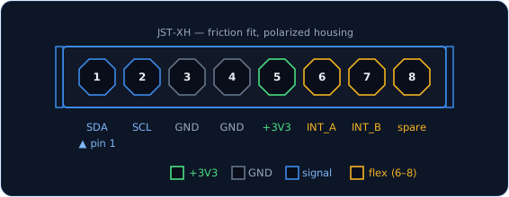
SDA/SCL run through 33 Ω series resistors at the host. Pins 6–8 are a flex block: pins 1–5 are fixed (SDA · SCL · GND · GND · +3V3); the last three default to INT_A / INT_B / spare but carry whatever a module needs — +5 V (e.g. a stepper driver's motor supply), an analog line, or an extra signal. View: into the cable-housing mating face, pin 1 marked.
SPI leg — J_SR
JST-XH 7-pin. The SPI-class sub-panel interface: 74HC165/74HC595 shift-register chains for encoder-bearing and fast-gauge panels. One per host chain, at the chain's end.
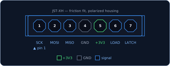
LOAD = '165 SH/LD̄ capture strobe, LATCH = '595 STCP publish strobe; 33 Ω series on
SCK/LOAD/LATCH at the host. The bus is dedicated — MISO is never shared with another SPI
device. View: into the cable-housing mating face, pin 1 marked. Pin order is verified
against the JST B7B-XH-A drawing and fabricated on PanelGroup base 0.2.0 (J10).
Switch & control wiring
Switch harnesses use JST-XH sized to the pin count (4/6/8), one shared GND per connector
group. Deep pin tables, net names, and the electrical rationale live in the discipline
reference (docs/_source/hardware-standards.md — Connectors and Shift-Register I/O
sections).